
The finite element method (FEM) is one of the most important engineering analysis techniques with its heat transfer applications, fluid mechanics, deformation mechanics, etc. The basic idea is to split the domain into a finite number of geometrically simple elements. The elements are connected through a finite number of nodes, and then they are comprehensively solved according to the equilibrium and deformation conditions.

Finite element modeling can be considered as a chain with 3 links. The first link is the spatial discretization and the numerical models. A physical object is simplified as a system of springs and masses that approximates its dynamic behavior. The second link is the solver performing the numerical time integration of the system of differential equations. The third link is the model describing the material behavior of the various material included in the simplified domain. Each of these links was getting stronger during the previous four decades.
1. Spatial discretization
During the 80s and 90s, the main limitation was the computational capacity and the inability to describe the domain with reasonable resolution. This resulted in the simulation of the low curvature buckling modes only. Thus, they consistently overestimated the structure’s energy absorption since high curvature modes were excluded from the simulation by outlaying the mesh. Too coarse meshes generally resulted in too stiff behavior of the energy-absorbing and highly deforming structural parts.
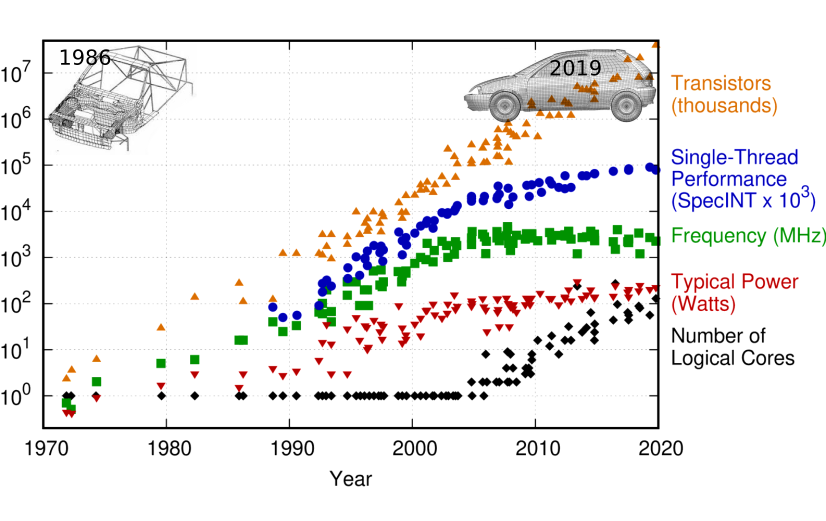
The image above shows the FE mesh for the first full-frontal crash simulation ever performed utilizing only 100s of elements. The image also shows the mesh utilizing millions of elements which is state-of-the-art in a crash simulation during 2019.
Since the 80s, the simulation activity has transformed from a numerical adventure to a precise scientific exercise.
2. Solver technology
Until the 2000s, the solver technology and the various algorithms were also not robust enough for most tasks. Some of the algorithmic deficiencies compensated for the errors due to the finite element mesh’s coarseness. Penetrations allowed due to failing contact algorithms and zero-energy modes in under-integrated shell elements would weaken the structural response and improve correlations between the numerical results and measurements. Due to the continuous improvement of the computational capacity and development of the algorithms, most of the problems within the link 1 and 2 disappeared. The models grew in resolution from a few hundred of thousands to a few million. The details of the components and the different joining techniques are commonly included nowadays. Improved algorithms for shells and contacts have been available in explicit codes for quite a while.
3. Material models: The weak link
Though the use of advanced materials like UHSS and composite materials have skyrocketed, there has not been much improvement in modeling the material behavior during the years. It is necessary to include the material’s ‘true’ strength to use the material to its fullest extent. It is difficult to predict the damage of high-strength material around holes, edges, and welds. And for this reason, including an advanced material model becomes crucial.
Though we have understood how a material deforms, hardens, and recovers driven by dislocations, it is not clear how dislocations contribute to material failure. During the manufacturing of a component, if it involves thermo-mechanical processing, there is most likely an associated phase change also. The effects of manufacturing, its phase compositions, and its contribution to the component’s properties need to be included to accurately predict its strength.